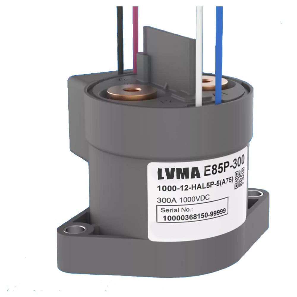
LME85V‑300M High‑Power DC Relay
LME85V‑300M High‑Power DC Relay
- 300A rated load current
- 1000VDC max switching voltage
- IP67 sealed construction
- Ultra‑low contact resistance: ≤0.3mΩ @ 200A
- High insulation: 1000MΩ @ 1000VDC
- 3kV AC dielectric strength
- Built‑in energy‑saving module
- Wide temperature range: −40°C to +85°C
- RoHS compliant
- Certified to IEC 60664‑1
- Compliant with ISO 9001, IATF 16949, ISO 14001, ISO 45001, IECQ QC 080000, ISO/IEC 27001
The LME85V‑300M is a high‑power, high‑voltage DC relay designed for heavy‑load industrial, energy storage, EV, and power distribution applications. It supports up to 300A continuous current and 1000VDC switching voltage, with IP67 protection, high insulation, and long‑term reliability under extreme conditions.
Key Features
- 300A rated load current
- 1000VDC max switching voltage
- IP67 sealed construction
- Ultra‑low contact resistance: ≤0.3mΩ @ 200A
- High insulation: 1000MΩ @ 1000VDC
- 3kV AC dielectric strength
- Built‑in energy‑saving module
- Wide temperature range: −40°C to +85°C
- RoHS compliant
- Certified to IEC 60664‑1
- Compliant with ISO 9001, IATF 16949, ISO 14001, ISO 45001, IECQ QC 080000, ISO/IEC 27001
Coil Specifications
| Item | 12VDC | 24VDC |
|---|---|---|
| Nominal Voltage | 12 VDC | 24 VDC |
| Must‑Operate Voltage | ≤9 VDC | ≤18 VDC |
| Must‑Release Voltage | ≥1 VDC | ≥2 VDC |
| Coil Power | 60W (holding: 4.3w) | 60W (holding: 4.3w) |
| Operate Time | ≤30 ms | ≤30 ms |
| Release Time | ≤10 ms | ≤10 ms |
Contact & Performance Data
Contact Ratings
- Contact form: 1 Form NO + 1 Form NC auxiliary
- Contact resistance: ≤0.3mΩ @ 200A; ≤150mΩ @ 1A
- Mechanical life: 2×10⁵ operations
- Max switching voltage: 1000VDC
- Max breaking current: 2000A @ 450VDC
- Max switching power: 450kW
Electrical Durability (Resistive Load)
- 1000VDC, 300A: 100 operations
- 800VDC, 300A: 500 operations
- 750VDC, 300A: 500 operations
- 450VDC, 300A: 1000 operations
- 450VDC, 2000A: 1 operation
Overload Withstand Time
- 300A: Continuous
- 450A: 400s
- 600A: 150s
- 1000A: 23s
- 2000A: 10s
Insulation & Environmental
- Insulation resistance: 1000MΩ @ 1000VDC
- Dielectric strength: 3kV AC for 1min
- Between main contacts
- Between contacts and coil
- Between main and auxiliary contacts
- Ambient temperature: −40°C ~ +85°C
- Humidity: 5% ~ 85%RH
- Vibration: 10Hz ~ 500Hz, 49m/s²
- Shock:
- Stability: 196m/s²
- Strength: 490m/s²
- Weight: 420g
- Terminals: M6 threaded
Dimensions (mm)
- Size: 84.5 × 62.5 × 73.0
- Mounting holes: 2×Ø7.5±0.1, pitch 70±0.3
- Wiring: Pin3 (+), Pin2 (−)
Important Operating Instructions
- Drive Mode
- Use fast rise‑time (step voltage) drive.
- Do not use slow‑rising voltage.
- Repeated switching <0.2s may cause failure.
- Energy‑Saving Module
- Coil switches to low power after 0.2s.
- Diode Caution
- Parallel diodes greatly increase release time and reduce life.
- Torque Requirements
- M6 mounting: 5–6 N·m
- M6 terminal: 6–8 N·m
- Cable
- Use ≥100mm² cable for high current.
- Safety Warning
- ≥1200A risk of contact welding
- ≥6000A / 20ms risk of contact blow‑open
- ≥8000A / 6ms risk of explosion and fire
- Always use proper fusing
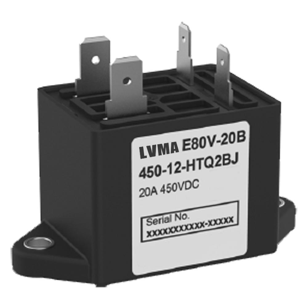
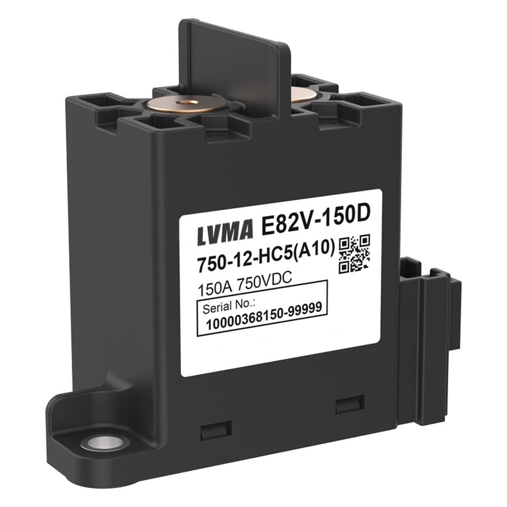
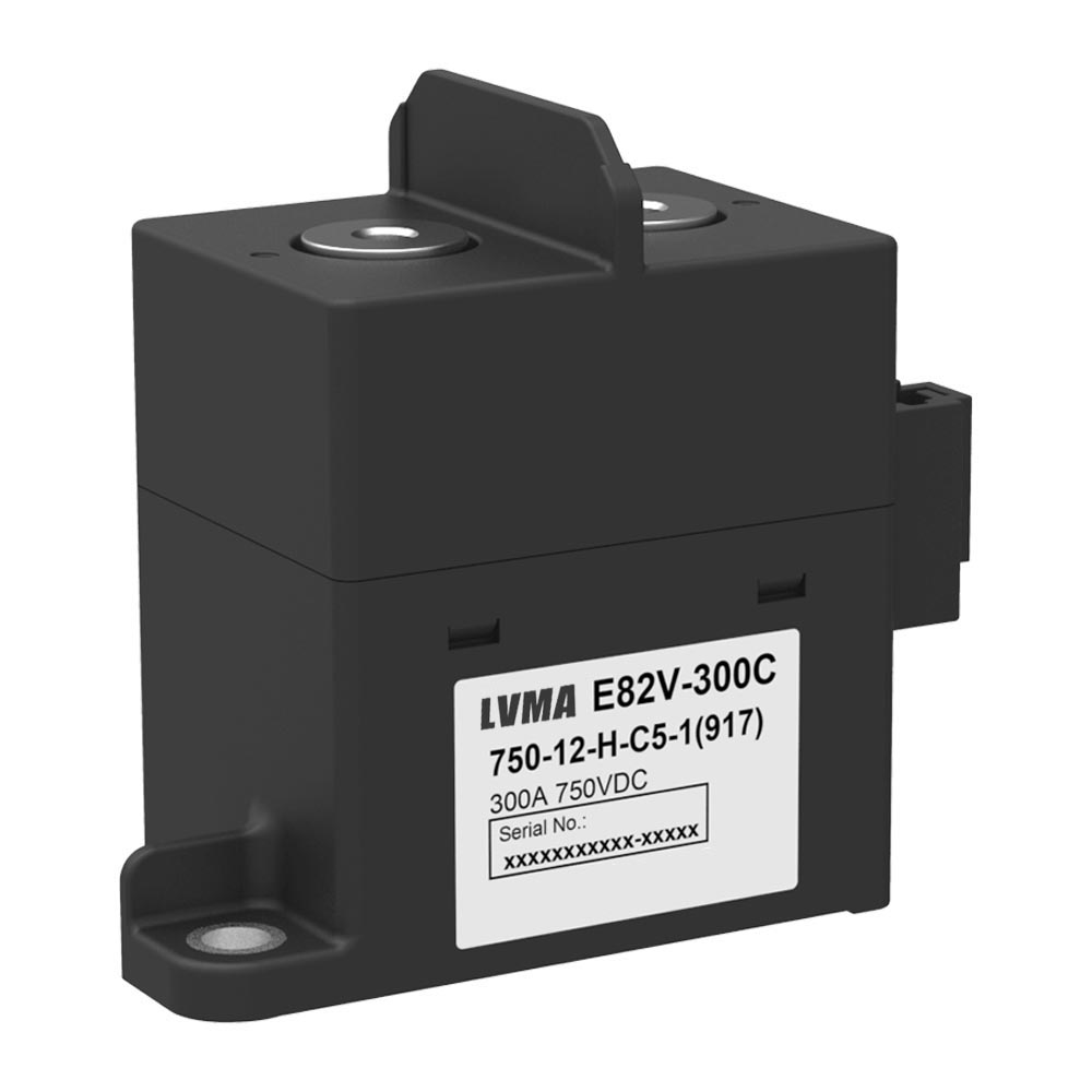
Related Products
Contact Us
Have questions about our products or services? Our team is here to help you with any inquiries.