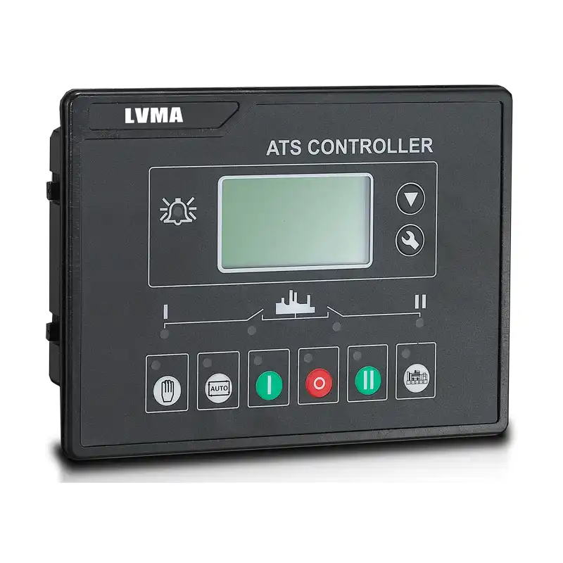
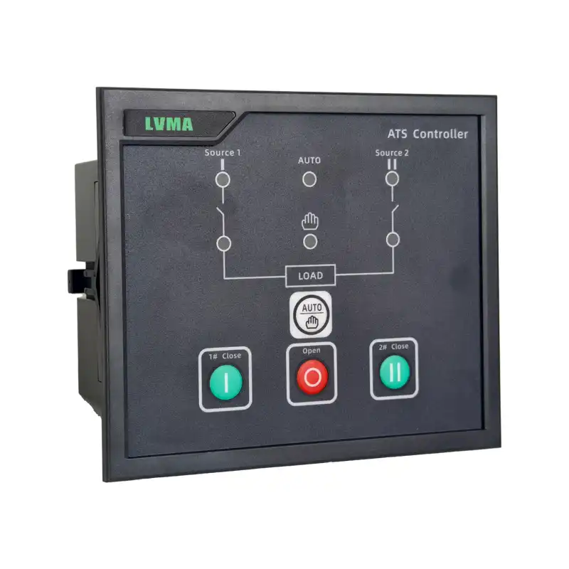
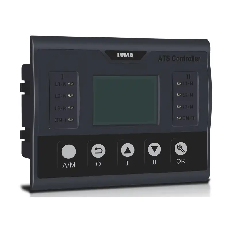
ATS Controller
Model:Y700,Y701B,Y703N
Monitoring Object:Two-circuit three-phase / single-phase power supply
Monitoring Content:Voltage, frequency, over-voltage, under-voltage, phase loss, phase error, phase reversal
Control Mode:Automatic switch & automatic reset, automatic switch & no reset, manual switch
Delay Function:Switching delay, reset delay (adjustable)
Switch Detection:Auxiliary contact detection of switch position, in-place feedback
Linkage Function:Generator start / stop control
Communication Interface:RS485 (Modbus RTU)
Operating Power Supply:AC220V / AC380V
Operating Environment:-20℃~+70℃Implementation
Standard:GB/T 14048.11, IEC 60947-6-1
The automatic transfer switch controller is the core control unit of a dual-power automatic transfer switch. It can reliably detect the voltage, frequency, phase loss, over/under voltage, and other statuses of the two power supplies, and monitor the switch body’s closing and opening positions and auxiliary contact feedback in real time. It can accurately determine whether the switch has executed the switching command, whether it is in position, and whether there is any jamming or malfunction. Electrical interlocking and logical judgment ensure safe and reliable switching. When the main power supply is abnormal, it automatically switches to the backup power supply and automatically switches back to the backup power supply after the main power supply is restored. It has self-testing, alarm, and protection functions, providing stable and reliable control and detection guarantees for continuous power supply.
| ATS Controller Function and Parameter Comparison Table in LVMA | |||
|
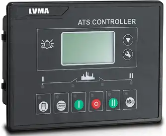
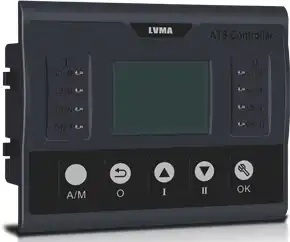
Product Pictures |
 |
 |
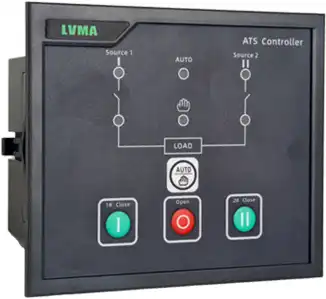 |
| Controller type | Y-700N | Y-703N | Y701B |
| Controller Installation | |||
| Installation method | Embedded installation (Mounted on panel door) | ||
| Connection mode | Terminal block | Terminal block + Customized cables | |
| Out line dimensions W*L*H | 211*155*55 | 170*126*56 | 150*122*62 |
| Hole size W*L | 186*141 | 150*111 | 130*111 |
| Characteristics Overview-Control Circuit | |||
| Compatible switch types | ACB/MCCB/MTS/ATS | MCCB/MTS/ATS | MCCB/MTS/ATS |
| Output ports/Number | 7: Programmable (pulse signal
or continuous model) |
3(Fixed)+3(Programmable) | 3(Fixed) |
| Input ports/Number | 6/Dry Contact
Input/Programmable |
6/Dry Contact
Input/Programmable |
4/Fixed |
| Rated operating voltage Ue | 230/400V | 230/400V | 230/400V |
| Rated insulation voltage Ui | 800V | 800V | 800V |
| Reference voltage for power detection Un | 220/380V | 220/380V | 220/380V |
| Controller(Min./Max.) | 70 ~ 120%Ue | 70 ~ 120%Ue | 70 ~ 120%Ue |
| Operating voltage range(V) | |||
| Operating voltage range(V) | Phase voltage 161 ~277 | Phase voltage 161 ~277 | Phase voltage 161 ~277 |
| Line voltage 280 ~480 | Line voltage 280 ~480 | Line voltage 280 ~480 | |
| Max.phase voltage of control power
Us(V) |
Phase voltage 277 | Phase voltage 277 | Phase voltage 277 |
| Max.measured line voltage of
control power Us(v) |
Line voltage 660 | Line voltage 480 | Line voltage 480 |
| Rated operating frequency | Adaptive 50/60Hz | Adaptive 50/60Hz | Adaptive 50/60Hz |
| Applicable Grounding System | IT/TN-C/TN-S/TT | TN-C/TN-S/TT | TN-C/TN-S/TT |
| Detection power(3-Phase products) | Common 3 P/Standby 3 P | Common 3 P/Standby 3 P | Common 3 P/Standby 3 P |
| Detection power(1-Phase products) | Common 1 P/Standby 1 P | Common 1 P/Standby 1 P | Common 1 P/Standby 1 P |
| Voltage loss judgment value | ≤30% Ue | ≤30% Ue | ≤30% Ue |
| Phase Failure Transfer | |||
| Detection power(3-Phase products) | Common 3 P/Standby 3 P | Common 3 P/Standby 3 P | Common 3 P/Standby 3 P |
| Detection power(1-Phase products) | Common 1 P/Standby 1 P | Common 1 P/Standby 1 P | Common 1 P/Standby 1 P |
| Phase failure judgment value (any phase) |
≤50V | ≤50V | ≤50V |
| Voltage loss and phase failure recovery Rated voltage Ue 230V,including 220V |
85% | 180V | 180V |
| Voltage loss and phase failure recovery Rated voltage Ue 400V,including |
85% | 310V | 310V |
| Under voltage Transfer | |||
| Detection power | Common 3 P/Standby 3 P | Common 3 P/Standby 3 P | Common 3 P/Standby 3 P |
| Under voltage setting range Rated voltage Ue 230V,including 220V |
50-100% | 100-200V | 100-200V |
| Factory default value | 80%Ue | 165V | 165V |
| Under voltage recovery value
Rated voltage Ue 230V,including 220V |
85%Ue | — | Under voltage value + 10-30V |
| Default+10V | Default+10V | ||
| Over voltage Transfer | |||
| Detection power | Common 3 P/Standby 3 P | Common 3 P/Standby 3 P | Common 3 P/Standby 3 P |
| Over voltage setting range Rated voltage Ue 230V,including 220V |
100-150%Ue | 200V-300V | 200V-300V |
| Factory default value | 120%Ue | 270V | 270V |
| Over voltage recovery value Rated voltage Ue 230V,including 220V |
115%Ue | — | Overv oltage value-10-30V |
| Default-10V | Default-20V | ||
| Frequency Abnormality Transfer | |||
| Detection power | Common 3 P/Standby 3 P | Common 3 P/Standby 3 P | Common 3 P/Standby 3 P |
| Frequency abnormality setting range | 0-70Hz | 0-70Hz | Only detection |
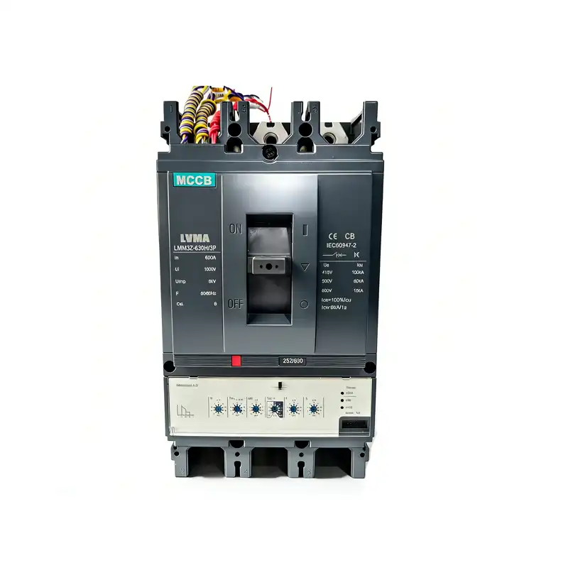
Related Products